

Our Focus Areas
Design for manufacturing (tool concept)
Moldflow
Measurement of theoretically deformed parts -
Feasibility analysis
3D Scanning and Measurements
Parts scanning and scanning of tool components
Measurement report of linear and GD&T dimension
Detailed analyse and list of needed improvements
Reverse engineering - part replica
DFM,
Moldflow
Feasibility of Injection Moulded parts

Expertise and
Flexibility
01
DFM - Design for manufacturing

DFM report is a bridge between product developers and mold makers.
It has been used in many manufacturing industries and has proven to be an effective way to increase efficiency and minimize failures.
A comprehensive DFM reporting mold manufacturing project will be the first step to success
Which information are part of DFM
-
Part and tool basic data
-
Raw material, shrinkage
-
Layout of cavity inserts
-
Parting line definition
-
Draft angles
-
Thickness design
-
Sink marks
-
Gate location
-
Cooling channels
-
Moldflow
-
Improvement proposals
02
Moldflow

Injection molding simulation - Moldflow is a powerful and useful tool that must be used properly.
The critical part is conducting the Moldflow in the inquiry phase, to do feasibility study and evaluation of requirements
It is advised that also part designers should be engage in Injection molding analyses in early design phase. To assess the initial feasibility of producing a part, it is essential to anticipate potential issues that may arise during the molding process, such as estimation of warpage and other relevant factors.
When we should do Injection Molding simulation – Moldflow and what are Moldflow benefits?
For toolmakers in the inquiry phase, conducting a Design for Manufacturing (DFM) report and Moldflow analysis is of utmost importance. These tasks are critical for ensuring the success of the manufacturing process.
The most important information which we need from Moldflow are:
-
Flow information – short shots, weld lines, air traps
-
Pack information – sink marks, gate freeze time
-
Warpage information
Based on those information we can optimise DFM report, change gate location, runner system and more.
03
Virtual measurement of theoretically deformed parts
3D theoretically deformed part is output of Moldflow analyse.
For feasibility study you need to check if you are able to reach given tolerances on the drawing. Usually deformations (warpage) and positioning of reference system are the main reasons why we have problems with reaching prescribed tolerances.
It is essentially the same process as measuring produced components (parts), except that you use a 3d warped or deformed model that is the result of a Moldflow analysis. Using GOM inspect software to do visual inspection comparison.


01
3D scanning of parts and tool components

You can quickly and accurately capture your object's shape and geometry using 3D scanning, a method of turning tangible objects into exact digital representations.
Millions of XYZ data points make up raw 3D scan data, sometimes known as "point clouds," which can be edited and distributed in a variety of native file formats.
This procedure gives you a complete digital model of your part that may be utilized for analysis, quality control, or reverse engineering at any stage of a typical manufacturing cycle.
02
Quality, Inspection Service and detailed analyse
Creating a report for the initial article inspection
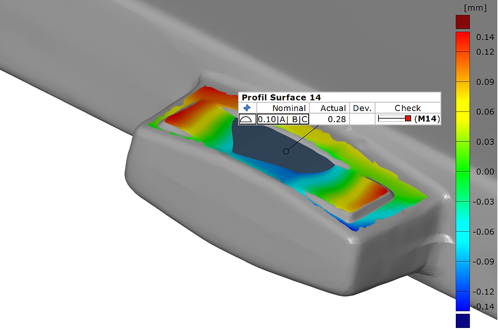
Full surface analysis including: surface defects, advanced GD&T using colour plots and nominal to actual comparison.
Understanding the influence of a datum system for your component using multiple alignments such as global best fit to understand how the datum features are performing
We are able to study and comprehend complex 3D shapes by using full surface data. Simple color plots across the whole surface of a component or assembly can be used to provide surface deviation analysis, surface profile mapping, and more complicated GD&T.
Sometimes it can be challenging to understand why some characteristics are red or where these deviations came from. What is the main reason.
In Matio the team of engineering experts can prepare detailed analyses to help you better understand the primary causes of deviations.
The toolmaker can use this information to identify what needs to be changed in the injection molding tool in order to meet the specified requirements.


DFM,
Moldflow
Feasibility of Injection Molded parts
Design for manufacturing (tool concept)
Moldflow
Measurement of theoretically deformed parts -
Feasibility analysis
3D Scanning and Measurements
Parts scanning and scanning of tool components
Measurement report of linear and GD&T dimension
Detailed analyse and list of needed improvements
Reverse engineering - part replica
Our Focus Areas